Learn Free Computer HardWare PC all Componets, Parts, Accessories

FLOPPY DISK DRIVE

USB DISK DRIVE :
Floppy Disk Drive 
                            A floppy disk is a data storage device  which a thin and flexible disk encased in a square or 
rectangle plastic shell floppy disk;s are read and written by a floppy disk drive. These are improved from 5inch, 160 KB to 3 inch, 1044MB. the power supply used in mini power connector.Dont remove the disk when the LED glows with the floppy disk.
                 The major parts of floppy disk drives are :
  1. Read write Head: These are used to read or write data from to the disk.
  2. Spindle Motor: It is used to spin the disk at either 300 or 360 rotation per minute.
  3. Stepper Motor :It is used to move the read write head and place it on desired track position.
  4. Mechanical Frame : It opens the protective window on the disk to allow the read write head to touch the dual sided diskette media. An external button allows the disk to be rejected.
  5. Circuit Board : It contains all the electronics to handle the data read from or written to the disk. It also controllers the stepper motor control circuit.
A floppy disk is a disk storage medium composed of a disk of thin and flexible magnetic storage medium, sealed in a rectangular plastic carrier lined with fabric that removes dust particles. They are read and written by a floppy disk drive (FDD).

Invented by IBM, floppy disks in 3.5-inch (89 mm), 5.25-inch (133 mm) and 8-inch (200 mm) forms were a ubiquitous form of data storage and exchange from the mid-1970s to the 2000s.
While floppy disk drives still have some limited uses, especially with legacy industrial computer equipment, they have been superseded by data storage methods with much greater capacity, such as USB flash drives, portable external hard disk drives, optical discs, memory cards, and computer networks.
                                           Basically, a floppy disk drive reads and writes data to a small, circular piece of metal-coated plastic similar to audio cassette tape. In this article, you will learn more about what is inside a floppy disk drive and how it works. You will also find out some cool facts about FDDs.
                                           An attempt to continue the traditional diskette was the SuperDisk (LS-120) in the late 1990s, with a capacity of 120 MB (actually 120.375 MiB), which was backward compatible with standard 3½-inch floppies. For some time, PC manufacturers were reluctant to remove the floppy drive because many IT departments appreciated a built-in file transfer mechanism that always worked and required no device driver to operate properly. However, manufacturers and retailers have progressively reduced the availability of computers fitted with floppy drives and of the disks themselves.
                         External USB-based floppy disk drives are available for computers without floppy drives, and they work on any machine that supports USB Mass Storage Devices. Many modern systems even provide firmware support for booting to a USB-mounted floppy drive.


COMPUTER HARDDISK

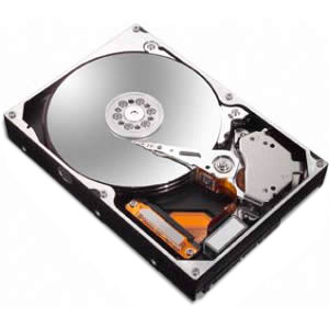
Computer Hard disk :
                                           The primary computer storage medium, which is made of one or more aluminum or glass platters, coated with a ferromagnetic material. Most hard disks are "fixed disks," which have platters that reside permanently in the drive. Almost all computers have an internal hard disk, and external units can be plugged in for additional storage or backup.


                                          The other type of hard disk is a "removable disk" encased in a cartridge, allowing data to be ejected from the drive for external storage or transfer to another party. Before high-speed Internet connections were common, removable SyQuest, Jaz and Zip cartridges were routinely shipped via the post office (see removable disk).

Three Major Categories: PATA, SATA and SCSI
Most hard disks are Parallel ATA (PATA), Serial ATA (SATA) or SCSI. SCSI drives have traditionally been found on servers and high-performance workstations and were the first drives used in fault-tolerant RAID systems. Today, ATA drives are widely used for RAID arrays. See IDE, PATA, SATA, SCSI and RAID.

Hard drives are low-level formatted at the factory, which records the original sector identification on the platters (see format program). See hard disk defect management.

Fast Rotation
Hard disks provide fast retrieval because they rotate constantly at high speed, from 5,000 to 15,000 RPM. Either to preserve battery life in laptops or to promote longevity, hard disks can be configured to turn off after a defined period of inactivity.

It Started in the Mid-1950s
In 1956, IBM introduced the RAMAC hard disk with platters two feet in diameter that held the equivalent of 
100,000 bytes. In the 1980s, desktop computer hard disks were introduced with 5MB using 5.25" platters (see ST506). Today's entry-level drives have at least 8,000 times more capacity. Platter size was reduced to 3.5" for desktops, 2.5" for laptops and 1" for handhelds. In 2004, Toshiba introduced the 0.85" drive (see below). See magnetic disk, floppy disk, Microdrive, drop protection and CAV.

POWER SUPPLY CONNECTORS

Power Supply Connectors:
                         The pc's power supply converts an high voltage AC current into lowvoltage DC current with is required for motherboard and disk drives.

                        Power supplies are designed as :
  1. AT power supply 
  2. ATX power supply.   We can't connect an AT styled power supply to an ATX power supplied motherboard. All power supplies have  3 connectors.
  1. Motherboard Power connector : Motherboard power connectors are used to connect motherboard to the power supply unit.
  2.  Molex Connector : Molex connectors are used to connect hard disk drives, CD and DVD media drives.
  3. Mini Connector :Mini connectors are used to connect 3.5 inch floppy drive.
             Wires and connectors are not perfect conductors. They have resistance. When current passes 
through wires and connectors there is a voltage drop and that energy is lost as heat. As long as you don't overload them the voltage drop and extra heat don't matter. But the losses get worse as the current rises. That's why you see some power cables with more that one wire for the same voltage. Having multiple wires reduces the losses. If you seriously overload a line, the wire can get fairly warm. The resistance of connectors tends to increase as they are plugged and unplugged so after enough uses they can overheat and even melt when passing a large current. So a lot of changes in connectors over time has to do with adding more wires and connectors to make sure that none of these problems occur.
           Some of the tables below provide the maximum wattage supported by a power cable and its associated power connector. Some specifications clearly spell out the maximum allowed wattage. Other specifications just provide the suggested connector and wire gauge and never specify a maximum wattage. And there's never really an absolute value to the maximum wattage anyway. If you draw a little more wattage then the maximum, the hardware doesn't immediately burst into flames. The voltage drop and power dissipation increase as you increase the current so there isn't a clear maximum wattage at which it stops working. Most of the specifications which spell out the maximum wattage provide a wide safety margin by defining a value which is far below the maximums supported by the connector and wire. If the table below provides an "Official cable/connector maximum wattage" then that specification has spelled out the maximum wattage. In most cases that wattage will be significantly below what can actually be handled by the suggested connector and wire. If the table provides an "Unofficial cable/connector maximum wattage" then that specification doesn't provide the maximum and the value in the table is a practical maximum wattage defined by the maximums for the connector and the suggested wire. An unofficial wattage doesn't have a wide safety margin built in because people differ on how much margin to provide. Some people happily use connector and wire maximums and other people like to have a wide safety margin.

COMPUTER USB PORT

Computer USB Port:
                   USB standards for : Universal Serial Bus.

                           USB (Universal Serial Bus) is an industry standard developed in the mid-1990s that defines the cables, connectors and protocols used for connection, communication and power supply between computers and electronic devices.
                         USB was designed to standardize the connection of computer peripherals, such as keyboards, pointing devices, digital cameras, printers, portable media players, disk drives and network adapters to personal computers, both to communicate and to supply electric power. It has become commonplace on other devices, such as smart phones, Pd As and video game consoles. USB has effectively replaced a variety of earlier interfaces, such as serial and parallel ports, as well as separate power chargers for portable devices.

                         As of 2008, about 2 billion USB devices were sold each year, and approximately 6 billion devices have been sold in total.
                            
                       A USB system has an asymmetric design, consisting of a host, a multitude of downstream USB ports, and multiple peripheral devices connected in a tiered-star topology. Additional USB hubs may be included in the tiers, allowing branching into a tree structure with up to five tier levels. A USB host may have multiple host controllers and each host controller may provide one or more USB ports. Up to 127 devices, including hub devices if present, may be connected to a single host controller
                     USB devices are linked in series through hubs. There always exists one hub known as the root hub, which is built into the host controller.
                      A physical USB device may consist of several logical sub-devices that are referred to as device functions. A single device may provide several functions, for example, a webcam (video device function) with a built-in microphone (audio device function). Such a device is called a compound device in which each logical device is assigned a distinctive address by the host and all logical devices are connected to a built-in hub to which the physical USB wire is connected. A host assigns one and only one device address to a function.
 

AGP PORT

AGP PORT:
                AGP Standards for: Accelerated Graphic Port.
                It is an interface specification developed by Intel . It is design specially for the throughput demands of 3D graphics in which the graphic controller can directly access main memory. It is of 32 bit wide and runs at 66MHz and has a band width of 266MBPS where as ,PCI bandwidth is 133 MBPS. Agp also has two optional faster modes with through put of 533 MBPS and 1.07 GBPS.

System Requirments of AGP:
  1. The chip set must support AGP.
  2. The motherboard must be equipped with an AGP bus slots.  
Features of AGP :
  1. Texturing also called as direct memory execute mode which allows textures to be stored on main memory.
  2. Side band addressing : It speed's up data transfer by sending command instructions in a seperate parallel channel.
  3. pipelining: It enables the graphics card to send instructions to gether instead of sendind one instruction at a time.
                           As computers became increasingly graphically oriented, successive generations of graphics adapters began to push the limits of PCI, a bus with shared bandwidth. This led to the development of AGP, a "bus" dedicated to graphics adapters.
                            The primary advantage of AGP over PCI is that it provides a dedicated pathway between the slot and the processor rather than sharing the PCI bus. In addition to a lack of contention for the bus, the point-to-point connection allows for higher clock speeds. AGP also uses sideband addressing, meaning that the address and data buses are separated so the entire packet does not need to be read to get addressing information. This is done by adding eight extra 8-bit buses which allow the graphics controller to issue new AGP requests and commands at the same time with other AGP data flowing via the main 32 address/data (AD) lines. This results in improved overall AGP data throughput.
                           In addition, to load a texture, a PCI graphics card must copy it from the system's RAM into the card's framebuffer, whereas an AGP card is capable of reading textures directly from system RAM using the Graphics Address Remapping Table (GART). GART reapportions main memory as needed for texture storage, allowing the graphics card to access them directly. The maximum amount of system memory available to AGP is defined as the AGP aperture.


TYPES OF RAMS

Different types of RAM's :
              
                               RAM is the acronym for 'random access memory' and is usually calculated in megabytes. A RAM chip is a module that holds freshly accessed information so that the central processing unit can have access to it. It is faster than reading from the hard drive and allows for easy access of recently stored data, information, and files. This means that all programs must be run through the RAM before they are usable.

                         There are two basic types of RAM, namely dynamic RAM and static RAM. A dynamic RAM is called so because it has to be constantly refreshed by the memory controller. The reason for refreshing is that the capacitors that hold the information or data have a built-in leak that can only be stopped by refreshing the information thousands of times in a second. This makes dynamic RAM slower and cumbersome compared to static RAM.
     FAM RAM:                                           
                         Fast Page Mode RAM was one of the earlier RAM models. This chip was introduced in 1990.FPM RAM operated at a clock speed of 25 megahertz, or MHz. The FPM RAM came in 30-pin and 72-pin models. It was able to achieve speed by using only the column address when the data was located in the same row as the previously accessed data.
   EDO RAM:
                 Extended Data Out RAM was introduced in 1994. This chip operated at a clock speed of 50 MHz. EDO RAM was used with the earlier models of Intel Pentiums prior to Pentium 4. EDO RAM had 72 Pins. This RAM was able to achieve faster speeds than FPM RAM by overlapping access cycles using the output buffer.
  SD RAM :
Synchronous Dynamic Random Access Memory had 168 pins. First shipped models operated at 66 MHz and later models had a speed of 100 MHz and then 133 MHz. SDRAM was introduced in 1996. This was the first RAM chip to synchronize with the microprocessor's clock speed.
 DDR SDRAM :
Double Data Rate SDRAM had 184 pins. Compatible with AMD and Intel microprocessors faster than 1 GHz, it improved on SDRAM and operated at clock speeds as fast as 266 MHz. It was twice as fast as SDRAM because it triggered off both the rising and falling edge of the clock signal. SDRAM on the other hand, used only the rising edge of the clock signal.


COMPUTER INTEL PROCESSOR

Computer  INTEL  Processor :
 
                      The central processing unit (CPU) is the portion of a computer system that carries out the instructions of a computer program, to perform the basic arithmetical, logical, and input/output operations of the system. The CPU plays a role somewhat analogous to the brain in the computer. The term has been in use in the computer industry at least since the early 1960s. The form, design and implementation of CPU have changed dramatically since the earliest examples, but their fundamental operation remains much the same.
                     On large machines, CPU require one or more printed circuit boards. On personal computers and small workstations, the CPU is housed in a single chip called a microprocessor. Since the 1970s the microprocessor class of CPU has almost completely overtaken all other CPU implementations. Modern CPU are large scale integrated circuits in small, rectangular packages, with multiple connecting pins.

                     Two typical components of a CPU are the arithmetic logic unit (ALU), which performs arithmetic and logical operations, and the control unit (CU), which extracts instructions from memory and decodes and executes them, calling on the ALU when necessary.
                     Not all computational systems rely on a central processing unit. An array processor or vector processor has multiple parallel computing elements, with no one unit considered the "center". In the distributed computing model, problems are solved by a distributed interconnected set of processors.
                         Monitoring processor usage on your computer is a key factor in tracking overall performance. While some software can bog down even the fastest new computers in certain situations, you may need to upgrade to a higher-power processor or buy a new computer if you detect heavy CPU usage on your system. Viruses and malware also use processors heavily. Fortunately, it is very easily to monitor CPU usage in Windows with a free tool included in the operating system.
                        Computer processors are constantly being refined and enhanced, but the fastest processors available on the market as of 2010 make billions of calculations per second and are rated as high as 4 GHz or 5 GHz.


TYPES OF COMPUTER CHIP SETS

Different types of computer chip sets :
       The chipset used with intel celeron, pentium 3 and pentium4 processor are : 
  1. Intel 810 chip set.
  2. Intel 815 chip set.
  3. Intel 845 chip set.
  4. Intel 850 chip set.
        Intel 810 chip set :
                        This integrated chip set offers innvotive features with compelling performance while lowering ovral syatem costs through smart integration.
  1. Intel hub architecture increased i/o performance allows better concurency for richer multimedia application.
  2. Low power sleep modes ,energy saving.
  3. Digital video output, allows connection of traditional TV or new digital flat panel displays, compatible with DIV specification.
  4. 2USB ports , plug and play.

   Intel 815 chip set
                 With the intel 815 chip set , intel has introduced innvotive technology to optimize fluxbility and stability in intel celeron and intel pentium 3 processor based PC

  1.  Intel hub architecture increased i/o performance allows better concurency for  next generation.
  2. System bus, supports 66MHz, 1oo MHz &133 MHz  configuration enhancing fluxbility for the value PC
  3. SDRAM,,optimized for 100/133MHz SDRAM.
  4. Dual usb, enables easy plug and play compatability.
  Intel 845 chip set :
              This chip set with support for PC800 RD RAM memory provides a balanced performance platform for the intel pentium 4 processor with 400 Mhz system bus.

  1. Intel hub architecture increased i/o performance allows better concurency for richer multimedia application.
  2. Low power sleep modes ,energy saving.
  3. Lan connect interface, multimedia network options taking advatages of intel single driver technology.
  4. Dual RD RAM capability, provides 3.2 gb memory bandwidth.
        Intel 850 Chip set :
         This chip set with support for PC800 RD RAM memory provides a balanced    performance platform for the intel pentium 4 processor with 400 Mhz system bus.

  1. Intel hub architecture increased i/o performance allows better concurency for richer multimedia application.
  2. Low power sleep modes ,energy saving.
  3. Lan connect interface, multimedia network options taking advatages of intel single driver technology.
  4. Dual RD RAM capability, provides 3.2 gb memory bandwidth.

COMPUER CHIP SET

Computer Chip set :

            The chip set is a group of chip. That helps the processor and other components on the PC to communicate with each other. It contains only the instructions to per formic functions.
            The functions of chip set are :
  1. It controls system memory.
  2. It controls motherboard bus.
  3. It controls the flow of bits between CPU and Devices.
  4. It also manages data transfer between the CPU memory and peripheral devices.
 
                   Your computer's chip set refers to a collection of chips all located on its motherboard. You may need to know your computer's chip set to do certain firmware upgrades or to locate drivers for it if you don't have your motherboard's original installation software. If your chip set isn't documented on your invoice or in your manual, you will need to open the computer to determine the chip set.
 
    A chip set is usually designed to work with a specific family of microprocessors. Because it controls communications between the processor and external devices, the chip set plays a crucial role in determining system performance.
In computing, the term chip set is commonly used to refer to a set of specialized chips on a computer's motherboard or an expansion card. In personal computers, the first chip set for the IBM PC AT was the NEAT chip set by Chips and Technologies for the Intel 80286 CPU.
 
        In the 1980s, Chips and Technologies, founded by Gordon Campbell, pioneered the manufacturing of chip sets for PC-compatible computers. Computer systems produced since then often share commonly used chip sets, even across widely disparate computing specialties. For example, the NRC 53C9x, a low-cost chip set implementing a SCSI interface to storage devices, could be found in Unix machines such as the MIPS Magnum, embedded devices, and personal computers.

CD ROM CONNECTOR

CD ROM Connector :
                                Audio system in CD-ROM is completely separate from PC sounds. When the computer tells CD-ROM to start playing audio CD then the CD-ROM starts play in git all by itself. The CD-ROM driver works just like normal CD player and does not need any PC CPU cycles to do the playback one it has been started. If CD playback seems to take up processor time in Windows the reason is the playback program which constantly ask from CD-ROM the current playing position and updates it to screen, the audio playback does not take any CPU processing power at all. 

                              CD-ROM drives have typically a headphone connector with volume control in the front panel. The headphone jack uses the CD-ROM directly you don't need to connect any CD-ROM audio cables to make this headphone connector to work. The audio cable from the CD to the sound card allows you to use the sound card amp and speakers to playback the sound from CD-ROM. The audio cable just connect the line level audio output form the CD-ROM drive to one PC sound card line level audio input dedicated to CD-ROM audio cable.

Why there is problems with CD-ROM audio connections:


There is quite much variety in CD-ROM audio connectors used in PC market. Many sound cards and CD-ROM drivers have their own special audio connector. All audio connectors basically carry line level (0.3-2 V pp) analogue audio signals from CD-ROM to computer sound card, but different connector types and pin outs cause too much problems nowadays.
The situation is little bit stabilizing because SPA MAC working group has done standardization on multimedia PCs. They have specified a standard interface connector and pin out which should be used computer sound cards and the audio cables which come with them. If your sound card and CD-ROM (which comes with audio cable) both meet MAC standards then you should not have problems in getting the sound working.

CD-ROM/Sound Card Audio Cable Standard for  MAC Components:

The following cable standards apply only to MAC components (CD-ROM drives or sound cards sold separately). Full systems and upgrade kits are not required to observe the following specification:
  1. A Multimedia PC CD-ROM drive component must include a cable to connect the drive's analog audio output connectorto an MPC sound card's analog audio input connector. 
  2. The cable's open sound card connector must be a female 4 pin Molex 70066-G,70400-G, or 70430-G connector with 2.54 mm .

HARD DISK DRIVE CONNECTOR

Hard disk drive connector :
                      Teletype Impulse provides a broad array of disc drive connectors. Our connectors are R Ohs compliant and are being used on most major platforms around the world. Teletype offers its cone point technology to insure maximum connectivity performance, and high temperature plastic materials are common. Telephone's products are designed to meet the global requirements of the computing industry. Custom design configurations are available upon request. 


                       Several different connectors and jumpers are used to configure the hard disk and connect it to the rest of the system. The number and types of connectors on the hard disk depend on the data interface it uses to connect to the system, the manufacturer of the drive, and any special features that the drive may possess. Instructions for setting common jumpers are usually printed right on the drive; full instructions for all jumpers will be in the product's manual, or on the manufacturer's web site.

                    Hard disk drives were introduced in 1956 as data storage for an IBM real time transaction processing computer and were developed for use with general purpose mainframe and mini computers.
                    As the 1980s began, hard disk drives were a rare and very expensive additional feature on personal computers (PCs); however by the late '80s, hard disk drives were standard on all but the cheapest PC.
                    Most hard disk drives in the early 1980s were sold to PC end users as an add on subsystem, not under the drive manufacturer's name but by Systems Integrators such as the Corvus Disk System or the systems manufacturer such as the Apple ProFile. The IBM PC/X in 1983 included an internal standard 10MB hard disk drive, and soon thereafter internal hard disk drives proliferated on personal computers.
                    External hard disk drives remained popular for much longer on the Apple Macintosh. Every Mac made between 1986 and 1998 has a SCSI port on the back, making external expansion easy; also, "toaster" Compact Macs did not have easily accessible hard drive bays (or, in the case of the Mac Plus, any hard drive bay at all), so on those models, external SCSI disks were the only reasonable option.

FLOPPY DISK DRIVE CONNECTOR

Floppy disk drive connector :

                  These are used for connecting floppy disk drives, hard disk drives, and CD drives.


The floppy disk interface uses what is likely the strangest cable of all those in PCs today.   It is similar to the standard A IDE cable in that it is usually a flat, gray ribbon cable.  It is unusual in terms of the number of connectors it has and how it is used to configure the setup of the floppy disks in the system.

The reason that the standard cable uses pairs of connectors for the drives is for compatibility with different types of drives. 3.5" drives generally use a pin header connector, while 5.25" drives use a card edge connector. Therefore, each position, A and B, has two connectors so that the correct one is available for whatever type of floppy drive being used. Only one of the two connectors in the pair should be used (they're too close together to use both in most cases anyway).   The more common pin header (IDC) connector is shown below.
                    The three-connector cables are found either in very old systems or in ones where the manufacturer was trying to save a few pennies. They reduce the flexibility of the setup; fortunately these cables can be replaced directly by the five-connector type if necessary.
You will also notice that there is an odd "twist" in the floppy cable, located between the two pairs of connectors intended for the floppy drives. Despite the fact that this appears to be a "hack" (well, it really is a hack), this is in fact the correct construction of a standard floppy interface cable.

ON BOARD I/O CONNECTORS

On Board I/O Connectors :
                 Devices like mouse & modem are connected to serial board. Printers and some other devices are connected to parallel board.
                 Recent systems are comming with USB ports to which majority of the components are connected.

An electrical connector is a conductive device for joining electrical circuits together. The Input Output Connectors connection may be temporary, as for portable equipment, or may require a tool for assembly and removal, or may be a permanent electrical joint between two wires or devices.
Connectors are important peripherals used to link two devices together. Since connector industry is a huge industry the models and types of connectors that arrive in markets are infinite. If you are a design engineer then, searching the right connectors suiting your designs can be a pain-stalking task. Taking the help of technology would surely lower the burden off your shoulder. It is easier to search among thousands of connectors available online by typing a few parameters, is less arduous than practically visiting each manufacturers, suppliers, or distributors website and offices.
Bad networking can nullify the effects of good engineered product line. Just having a wide product line of efficient, archetype connectors won’t result to good business. For this, it requires a hybrid network of suppliers, distributors and representative who further the reach of your product deep in the market. Our website is a platform that can help you develop chain of Input Output Connectors supplier, distributors and representatives engaged in the online selling of connectors. Our database comprises of the most branded and trusted names of the electronic industries, hence you always benefit by associating yourself with us.
Distributors and suppliers are able to inculcate newer models into their catalogs, thus multiplying their prosperity chances. Our online catalogs has over 100’s of connectors listed and is still growing in number.
Connectors are devices to connect any plug and socket and help to link two devices together. It affects whole electronic system if not designed or constructed properly, because it is a basic linking media or pointer between two data structures.
   Features:
  • To defend from loss when memory card was ejected, half-lock structure is adopted.
  • Media detection switch adopts highly reliable contact structure with sliding at ON/OFF.
  • Media detection switch surely detects timing when media are inserted.
  • Available for both SD Memory Card and MultiMediaCard.
  • Compact size and low-profile.
  • Compliant to FCC standards.
  • Connected with a cables and wide variety are available
  • Termination to pre-inserted contacts.
Applications:
  • In Telephones, Fax machines,
  • Wireless applications,
  • Modems, Intercoms, etc.

EXPANSION SLOTS ON THE MOTHERBOARD

Expansion slots on the motherboard :
          System expansion is possible using expansion slots. If you want to add a new device to a computer other than what is on the motherboard you need an expansion slots.
             Expansion slots is the back bone of the computer. If you want add a new device to your computer other than what is on the motherboard we need an expansion slots.
            The expansion slots are recognized according to the no.of bits that they can transfer at a time an bus architecture. 
  1. Address , data and control buses on the motherboard are connected to different expansion slots cards through expansion slots on the motherboard.
  2. A new device can be connected to your basic computer using these expansion cards.

        
The expansion card (also expansion board, adapter card or accessory card) in computing is a printed circuit board that can be inserted into an expansion slot of a computer motherboard or back plane to add functionality to a computer system via the expansion bus.
            One edge of the expansion card holds the contacts (the edge connector) that fit exactly into the slot. They establish the electrical contact between the electronics (mostly integrated circuits) on the card and on the motherboard.
           Connectors mounted on the bracket allow the connection of external devices to the card. Depending on the form factor of the motherboard and case, around one to seven expansion cards can be added to a computer system. 19 or more expansion cards can be installed in back plane systems. There are also other factors involved in expansion card capacity. For example, most graphics cards on the market as of 2010 are dual slot graphics cards, using the second slot as a place to put an active heat sink with a fan.
          Some cards are "low-profile" cards, meaning that they are shorter than standard cards and will fit in a lower height computer chassis. (There is a "low profile PCI card" standard that specifies a much smaller bracket and board area). The group of expansion cards that are used for external connectivity, such as network, SAN or modem cards, are commonly referred to as input/output cards (or I/O cards).
         The primary purpose of an expansion card is to provide or expand on features not offered by the motherboard. For example, the original IBM PC did not provide graphics or hard drive capability. In that case, a graphics card and an ST-506 hard disk controller card provided graphics capability and hard drive interface respectively.
        In the case of expansion of on-board capability, a motherboard may provide a single serial RS232 port or Ethernet port. An expansion card can be installed to offer multiple RS232 ports or multiple and higher bandwidth Ethernet ports. In this case, the motherboard provides basic functionality but the expansion card offers additional or enhanced ports.


CACHE MEMORY

Cache Memory :
                       It is a fast memory Which lives in between CPU & RAM. The frequently used data is placed in cache memory .CPU can access Cache memory faster than RAM. Hence it improves the performance of  the system.
                    
                  A CPU cache is a cache used by the central processing unit of a computer to reduce the average time to access memory. The cache is a smaller, faster memory which stores copies of the data from the most frequently used main memory locations. As long as most memory accesses are cached memory locations, the average latency of memory accesses will be closer to the cache latency than to the latency of main memory.
                When the processor needs to read from or write to a location in main memory, it first checks whether a copy of that data is in the cache. If so, the processor immediately reads from or writes to the cache, which is much faster than reading from or writing to main memory.
              Most modern desktop and server CPUs have at least three independent caches: an instruction cache to speed up executable instruction fetch, a data cache to speed up data fetch and store, and a translation lookaside buffer (TLB) used to speed up virtual-to-physical address translation for both executable instructions and data. Data cache is usually organized as a hierarchy of more cache levels (L1, L2, etc.; see Multi-level caches).
         When the processor needs to read or write a location in main memory, it first checks whether that memory location is in the cache. This is accomplished by comparing the address of the memory location to all tags in the cache that might contain that address. If the processor finds that the memory location is in the cache, we say that a cache hit has occurred; otherwise, we speak of a cache miss. In the case of a cache hit, the processor immediately reads or writes the data in the cache line. The proportion of accesses that result in a cache hit is known as the hit rate, and is a measure of the effectiveness of the cache for a given program or algorithm.
             In the case of a miss, the cache allocates a new entry, which comprises the tag just missed and a copy of the data. The reference can then be applied to the new entry just as in the case of a hit. Read misses delay execution because they require data to be transferred from a much slower memory than the cache itself. Write misses may occur without such penalty since the data can be copied in the background. Instruction caches are similar to data caches but the CPU only performs read accesses (instruction fetch) to the instruction cache. Instruction and data caches can be separated for higher performance with Harvard CPUs but they can also be combined to reduce the hardware overhead.

ROM MEMORY

ROM Memory :
             ROM standards for : Read Only Memory.
     One major type of memory that is used in PCs is called read-only memory, or ROM for short. ROM is a type of memory that normally can only be read, as opposed to RAM which can be both read and written. There are two main reasons that read-only memory is used for certain functions within the PC.
  
While the whole point of a ROM is supposed to be that the contents cannot be changed, there are times when being able to change the contents of a ROM can be very useful. There are several ROM variants that can be changed under certain circumstances; these can be thought of as "mostly read-only memory". :^) The following are the different types of ROM with a description of their relative verifiability:
  • ROM: A regular ROM is constructed from hard-wired logic, encoded in the silicon itself, much the way that a processor is. It is designed to perform a specific function and cannot be changed. This is inflexible and so regular ROMs are only used generally for programs that are static (not changing often) and mass-produced. This product is analogous to a commercial software CD-ROM that you purchase in a store.
  • Programmable ROM (PROM): This is a type of ROM that can be programmed using special equipment; it can be written to, but only once. This is useful for companies that make their own ROM from software they write, because when they change their code they can create new Proms without requiring expensive equipment. This is similar to the way a CD-ROM recorder works by letting you "burn" programs onto blanks once and then letting you read from them many times. In fact, programming a PROM is also called burning, just like burning a CD-R, and it is comparable in terms of its flexibility.
  • Erasable Programmable ROM (EPROM): An PROM is a ROM that can be erased and reprogrammed. A little glass window is installed in the top of the ROM package, through which you can actually see the chip that holds the memory. Ultraviolet light of a specific frequency can be shined through this window for a specified period of time, which will erase the EPROM and allow it to be reprogrammed again. Obviously this is much more useful than a regular PROM, but it does require the erasing light. Continuing the "CD" analogy, this technology is analogous to a reusable CD-RW.
  • Electrically Erasable Programmable ROM (EEPROM): The next level of erasability is the EEPROM, which can be erased under software control. This is the most flexible type of ROM, and is now commonly used for holding BIOS programs. When you hear reference to a "flash BIOS" or doing a BIOS upgrade by "flashing", this refers to reprogramming the BIOS EEPROM with a special software program. Here we are blurring the line a bit between what "read-only" really means, but remember that this rewriting is done maybe once a year or so, compared to real read-write memory (RAM) where rewriting is done often many times per second!

RAM MEMORY

RAM Memory :
         RAM standards for : Random Access Memory.
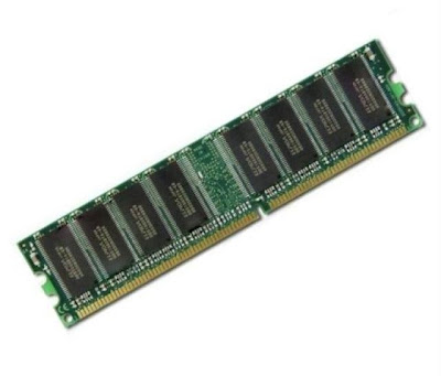
              It is called as random Access Memory  because the CPU can access any location in memory at random and retrieve binary information with in a fixed interval of time. It is used for storing programs temporary. In recent system RAM is found in dual in line memory module (DIMM).
 
                                                                        Random-access memory (RAM) is a form of computer data storage. Today, it takes the form of integrated circuits that allow stored data to be accessed in any order with a worst case performance of constant time. S
                    The two main forms of modern RAM are static RAM (SRAM) and dynamic RAM (DRAM). In static RAM, a bit of data is stored using the state of a flip-flop. This form of RAM is more expensive to produce, but is generally faster and requires less power than DRAM and, in modern computers, is often used as cache memory for the CPU. DRAM stores a bit of data using a transistor and capacitor pair, which together comprise a memory cell. The capacitor holds a high or low charge (1 or 0, respectively), and the transistor acts as a switch that lets the control circuitry on the chip read the capacitor's state of charge or change it. As this form of memory is less expensive to produce than static RAM, it is the predominant form of computer memory used in modern computers.
                Both static and dynamic RAM are considered volatile, as their state is lost or reset when power is removed from the system. By contrast, Read-only memory (ROM) stores data by permanently enabling or disabling selected transistors, such that the memory cannot be altered. Writeable variants of ROM (such as EEPROM and flash memory) share properties of both ROM and RAM, enabling data to persist without power and to be updated without requiring special equipment. These persistent forms of semiconductor ROM include USB flash drives, memory cards for cameras and portable devices, etc. As of 2007, NAND flash has begun to replace older forms of persistent storage, such as magnetic disks and tapes, while NOR flash is being used in place of ROM in netbooks and rugged computers, since it is capable of true random access, allowing direct code execution.
             ECC memory (which can be either SRAM or DRAM) includes special circuitry to detect and/or correct random faults (memory errors) in the stored data, using parity bits or error correction code.
            In general, the term RAM refers solely to solid-state memory devices (either DRAM or SRAM), and more specifically the main memory in most computers. In optical storage, the term DVD-RAM is somewhat of a misnomer since, like CD-RW, a rewriteable DVD must be erased before it can be rewritten.